(In order to fulfil the assignments criteria I have to merge two process posts together, as such I have combined my simplest model with another.)
Model 5 – Booth Seat
Not every one of my assets resulted in a long and in depth modelling process. Some, such as the booth seat didn’t lend itself to a overly complicated design. There were a few tweaks I wanted to make to my model from the references in an effort to add detail and interest. I knew I wanted to add detail to the seat base using extrudes. This was to A, make the design more interest and B, help tie my booth seat in with the bar stool I had made previously. The bar stool I made used the same extruding technique along the seat base as I did here, tying the two chairs together nicely.

DrinkStuff.com [Product]. Retro Diner Booth Double Seat Duck Egg Blue. [Accessed 22/11/2020]
What I like about this reference is the colour scheme, which I would also extend along the bench cushion to match the back piece. Also the way the bench cushion sits against the full size back rest looks like something which would have been produced on mass in the 1950’s

Alibaba.com [Product]. modern red single american diner booth seating.[Accessed 22/11/2020]
This reference is what gave me the idea of making my booth seat double sided. I think this is a clever way of adding interest to an otherwise quite plain model.

Fig.1 
Fig.2

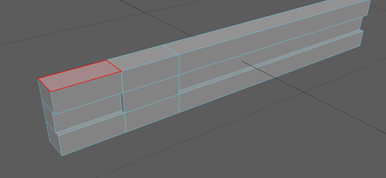
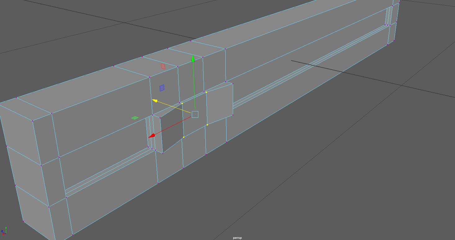
I began with a basic square, which I scaled to give me the size I wanted. After which I used the edge loops tool to give me two evenly spaced edge loops, running the rim of the square. These I extruded inwards to give me a similar design to that of the bar stool I previously made (Fig.1). I also added an edge loop to the middle of the shape, which I then extruded outward to give me the wooden from on which the cushions will sit (Fig.2)

Fig.3 
Fig.4


Next I started making the bench cushion. I only had to make one, which I would then obviously duplicate for the mirrored side. I used another cube for this, which I formed into a rectangle size I liked and bevelled the overhanging bottom edge, which brought my cushion in line with the base similar to that found in my first reference (Fig.3). With the cushion in place I added three evenly spaced edge loops and extruded. This gave me the nice groves in the cushioning that was present in the first reference image (Fig.4). I also bevelled along the top edge to make it seem like a stuffed cushion.

Fig.5 
Fig.6 
Fig.7


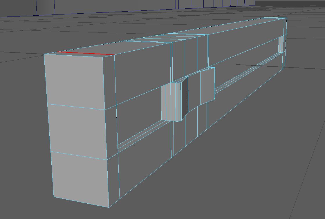
For the back cushion I copied the steps I took the for the bench seat. I used a cube which I shaped, and then used the edge loops and extruded to give the impression the two-piece lined up (Fig.7). With the cushions done I added an edge loop through the middle of the stand between the cushions and extruded inwards (Fig.5). This simply served to add detail to the design which otherwise looked a little unfinished. There was some issues with my topology, mostly caused due to the bevelling I had done. However I soon sorted this using the multi cut tool (Fig.6)
At this stage the seat was done, but I didn’t really feel satisfied with what I had produced. I knew this wasn’t going to be as in depth an asset as some of my other choices, but I still wanted to find a way to implement some method I had not used before. With this in mind I decided I would decorate the asset with some cushions. This would allow me to experiment a little and try out a new method for creating them, much like I did using ncloth for the fruit table scene in my pre assignment 3d work.
I followed the above video in creating my cushion, making the obvious adjustments such as using a more squared shape rather than a rectangle to make the pillow into a cushion. I started with a cube, which I then went into the animation options and used the pressurise tab to make the square pop itself into a cushion.

Fig.8 
Fig.9


Once I had my cushion inflated to a size I liked I paused the animation and deleted all history. Removing my cushion from the animation mode and giving me a still object which I could use.

Fig.10
Once I had my cushion as a still object I bevelled the top and bottom edge for the seems of the cushion (Fig.10), in a process called piping which will allow me to UV and texture the cushions later.

Fig.11

Overall, I would say modelling this asset was easy and straight forward. Nothing went too wrong and I am happy with the result. I know that this isn’t a complicated design, and in hindsight feel like this would have made a good first asset to do. I don’t foresee there being much issue with the UV of this asset or the texturing as there are really just three different parts. The wooden frame, the red vinyl and the white vynl for detailing.
A nicely done, easy to make asset.
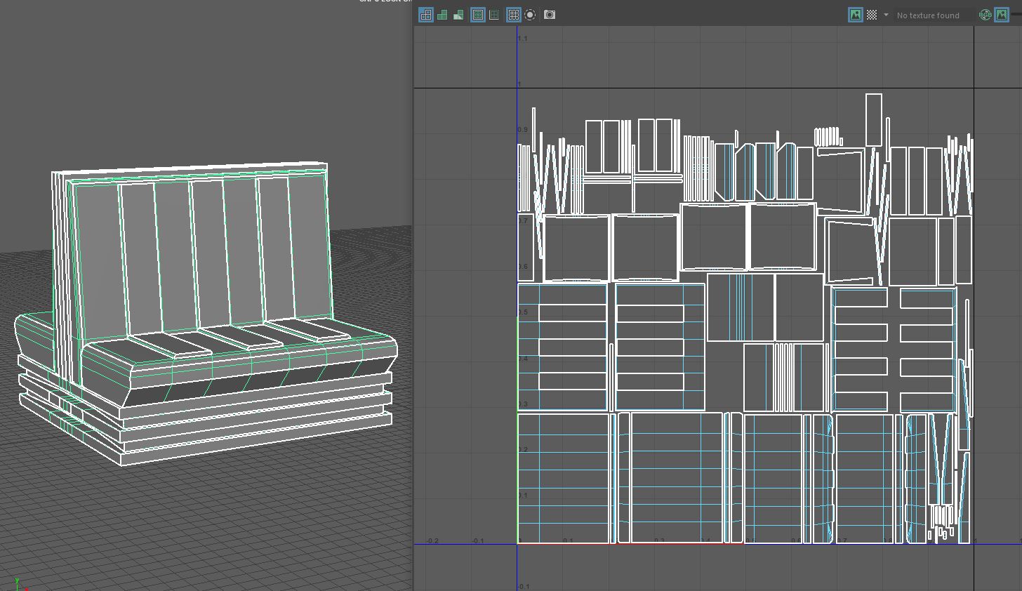
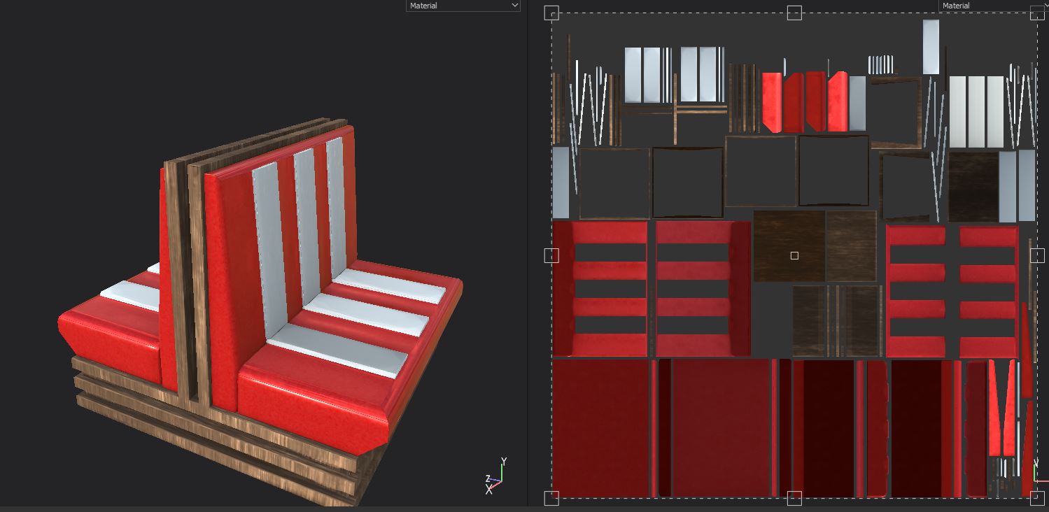
UV
With such a simple asset it makes sense that this is the most basic UV I ended up with. Hoenstly, just the automatic version I got was pretty close to the finished version, all I had to do was add cuts to the bevelled edges of the cushions so that the padding would bake well enough for the finished model.
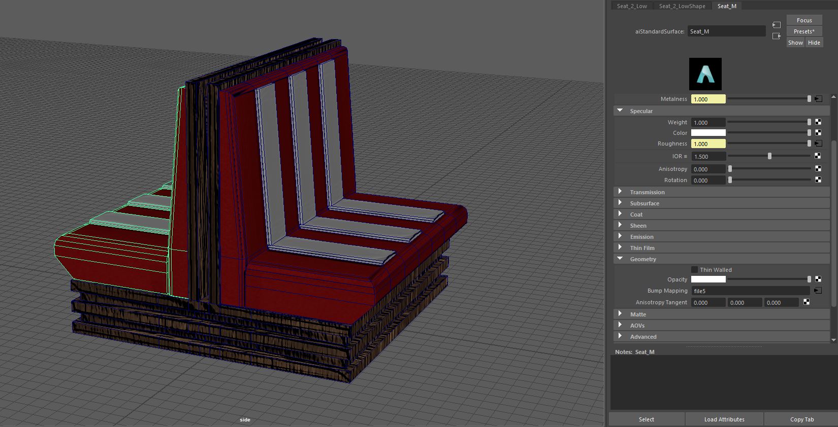
Texturing
The errors with the bake did not really affect this model as much as they did the others. While there was the usual dead zones around the edges (Fig.3) and a little artefacting around where the smoothed cushioning and rough collided none of it was visible in the final render.
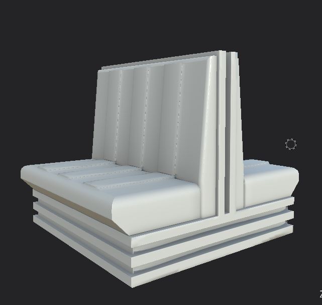
Fig.1 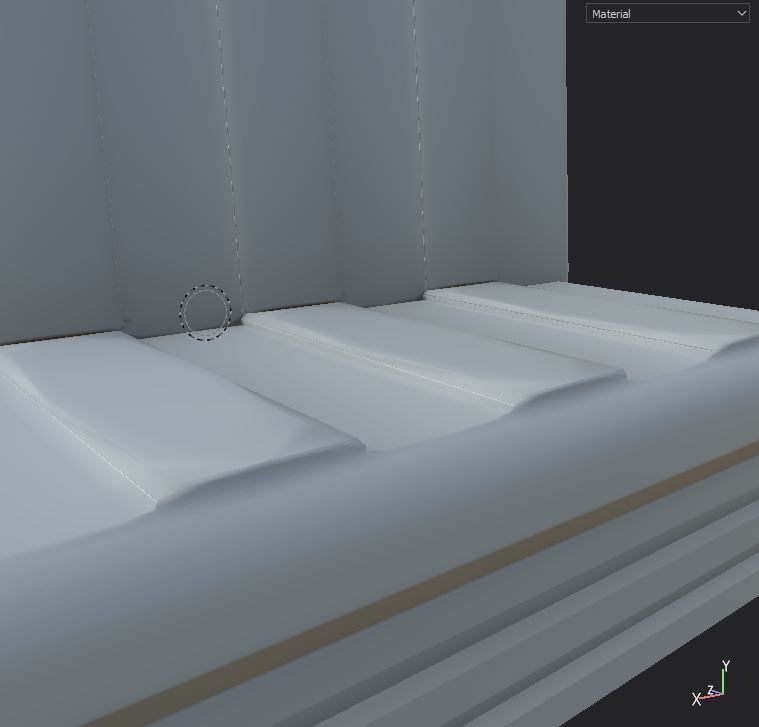
Fig.2 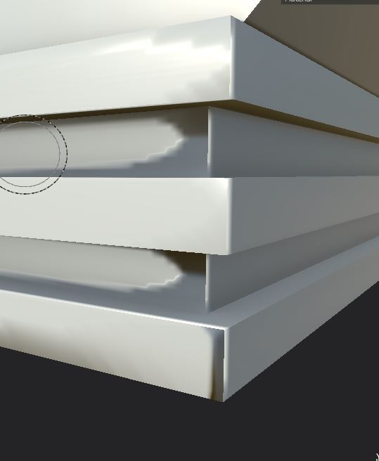
Fig.3
This model is super simple, and so was the texturing process. I simple selected a nice wood to use for the frame (Fig.4). Then used the black latex material and changed the base colour to a nice red (Fig.5) before repeating this with a white base colour for the cushioning (Fig.6). This resulted in a model with the textures that match the ceiling light and the bar stool, helping to tie all the assets of my asset pack together.
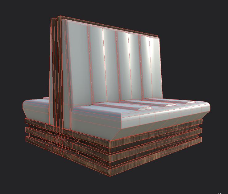
Fig.4 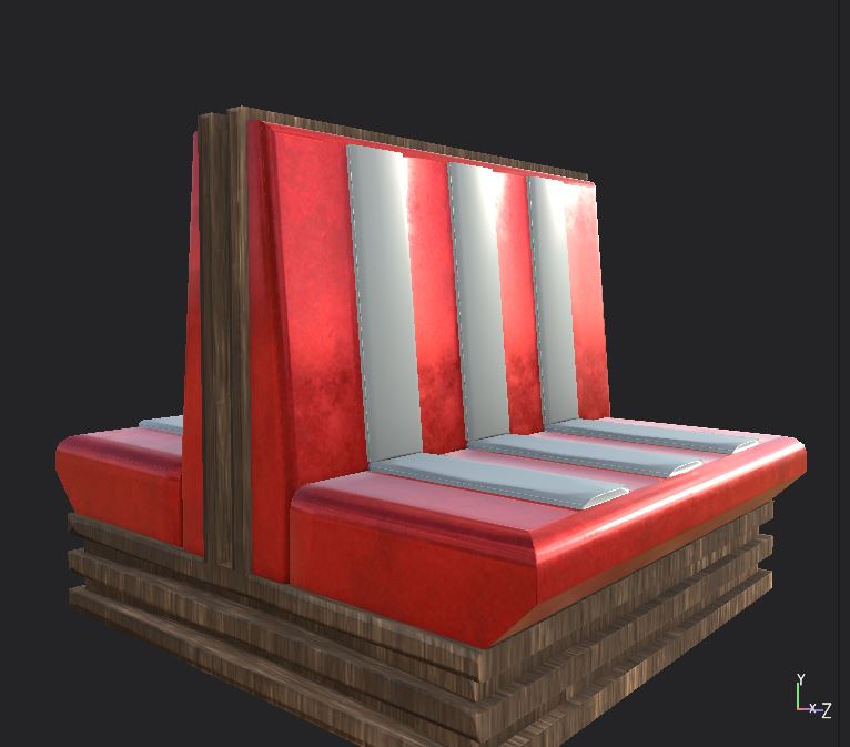
Fig.5 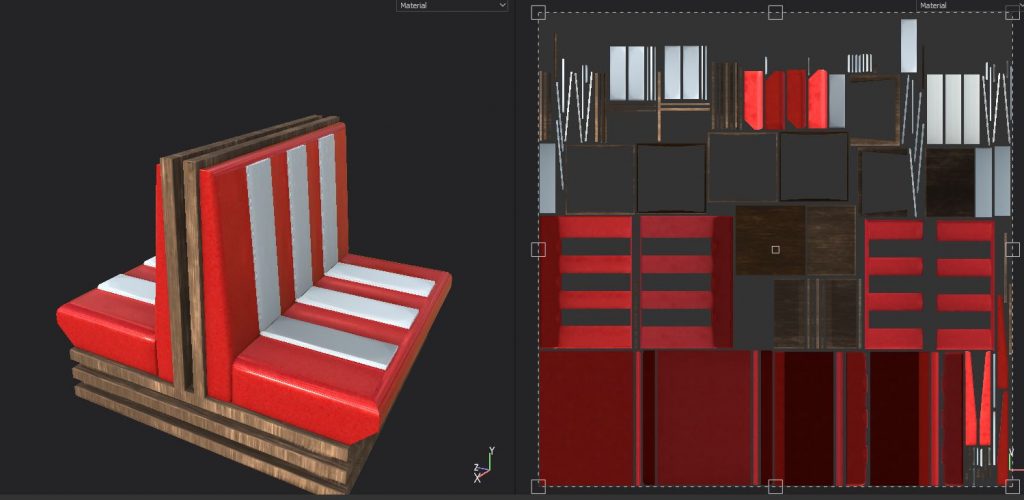
Fig.6 
Fig.7
Final renders can be found here
Referencing
Alibaba.com [Product]. modern red single american diner booth seating. Available online: https://www.alibaba.com/product-detail/modern-red-single-american-diner-booth_60677515166.html [Accessed 22/11/2020]
DrinkStuff.com [Product]. Retro Diner Booth Double Seat Duck Egg Blue. Available online: https://www.drinkstuff.com/products/product.asp?ID=14769 [Accessed 22/11/2020]
Hermes, Mike (2017) How to model a 3D Pillow in Maya 2018 in 5 minutes [Video]. Available online: https://www.youtube.com/watch?v=y__tsqaKxxk&ab_channel=MikeHermes [Accessed 22/10/2020]
Model 6 – Vintage TV

Brueton,c (2011). Our View Event – Media Focus. Accentuate [Online Article]. [Accessed 24/11/2020]
I liked the surround of this reference, also I think the four legs look nicer than having the box itself sit on the floor. Though I like the small screen of the other reference.

USHistory.org. (2020). Land of Television. [Online Resource]. [Accessed 24/11/2020]
I thought the prominent speaker grill looked nice in this model, and the prominent dials was something I incorporated in my design.
Production
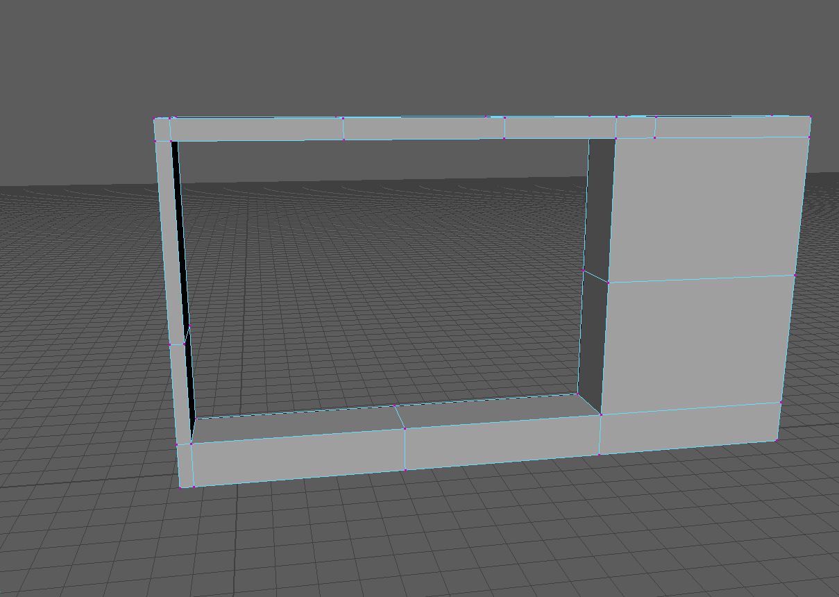
I ran into a few problems with this design. One of which really bugs me as it resulted with me ending up with a design I did not like as much as my original. Firstly, I began with a basic cube, which I stretched out into the shape above (Fig.1). After I had this shape, I merged the vertex joining the two ends of the shape together into one (Fig.2). Then I extended the edges of the shape, which gave a nice, rounded effect (Fig.3).
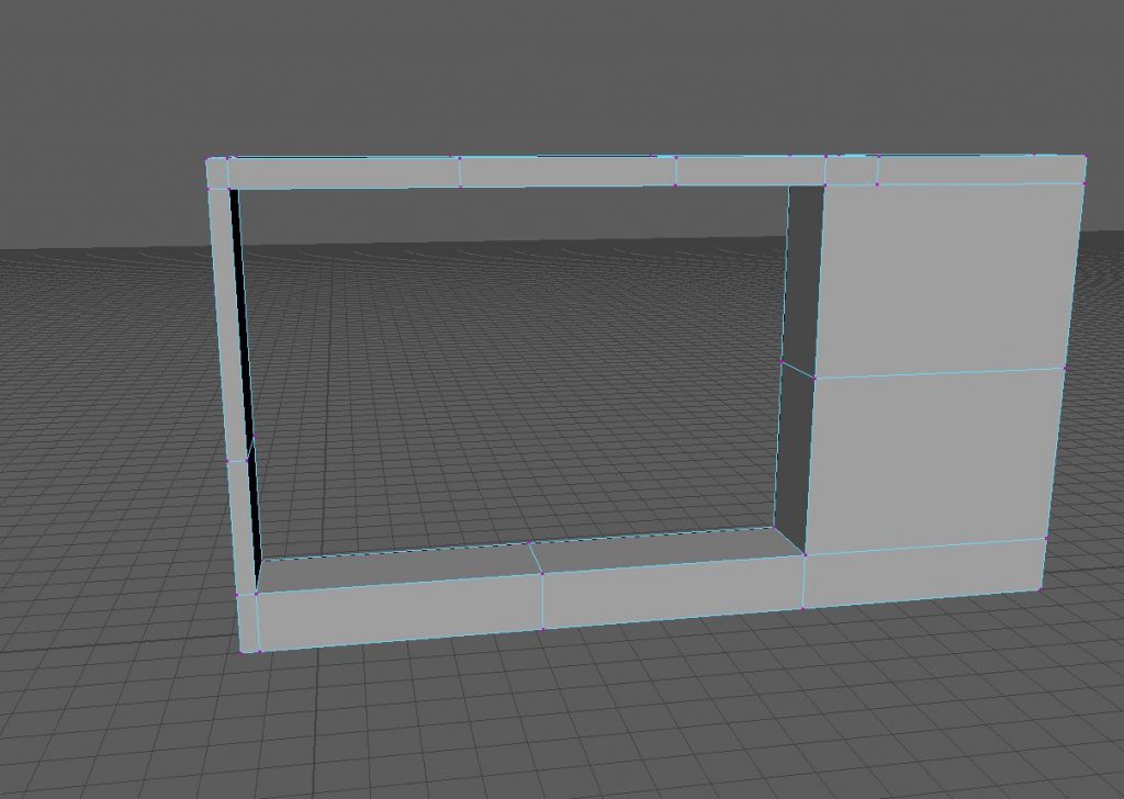
Fig.1 
Fig.2 
Fig.3 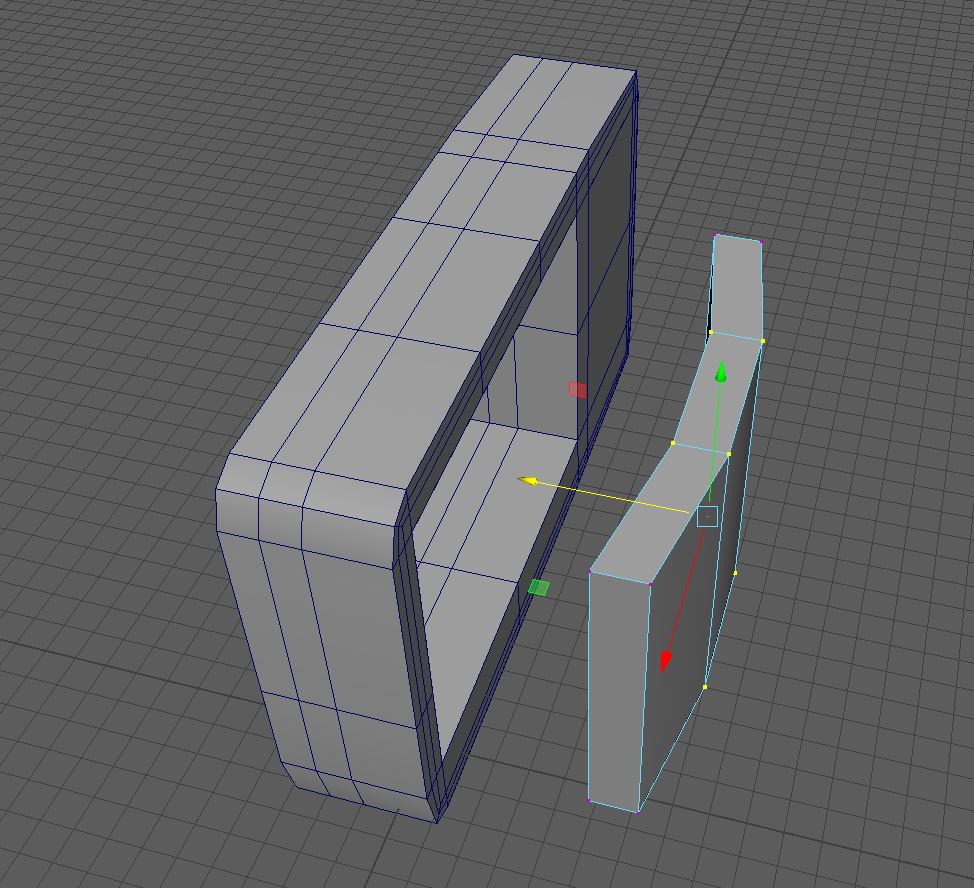
Fig.4 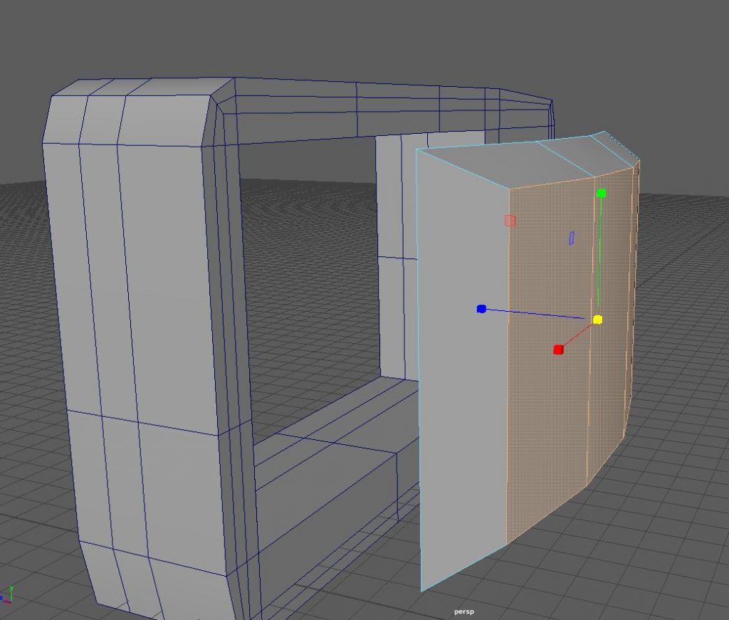
Fig.5
With the body made, I created the screen. As shown in the reference, old TV screens were not flat, and were not square. I began with a basic cube, which I shaped into a rectangle. Then, I used the mesh tool to add two evenly spaced edge loops in the centre of the shape. Which I could then go into vertex mode and moved the shaped out to give me a curved rectangle (Fig.4). I also bevelled the face of the shape, and manipulated the new, offset faces into a shape I liked using the move tool (Fig.5).
Here I made my first mistake, fortunately I caught it early so it didn’t cause to much of a delay. The method I had used to create the body, using a square to create a hollow shape and vertexing the faces together resulted in me not being able to bevel the edge of the hole like I intended. I got around this by using a more basic method of just creating a square which I then increased the size of (Fig.6). It occurred to me here that the back of the tv won’t be seen by the viewer and as such I don’t need to bother modelling the extended back TV’s had back then. So, this method worked well.
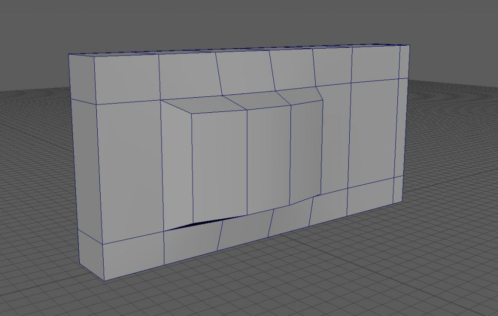
Fig.6 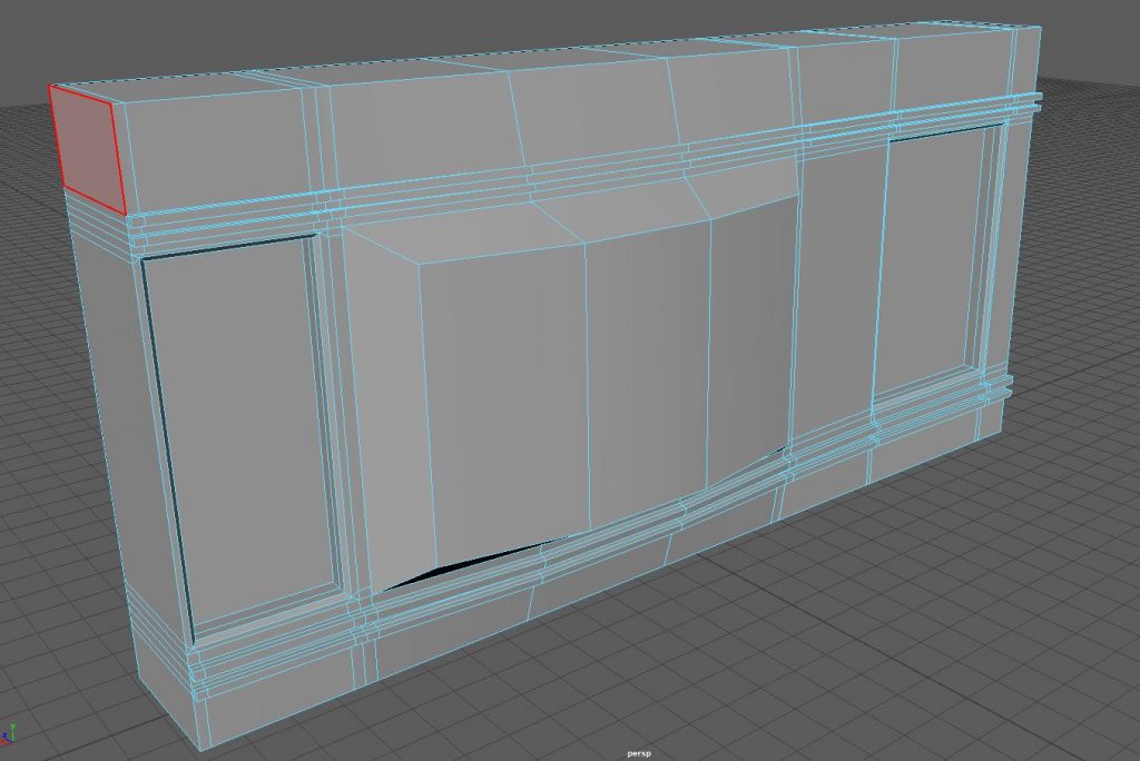
Fig.7

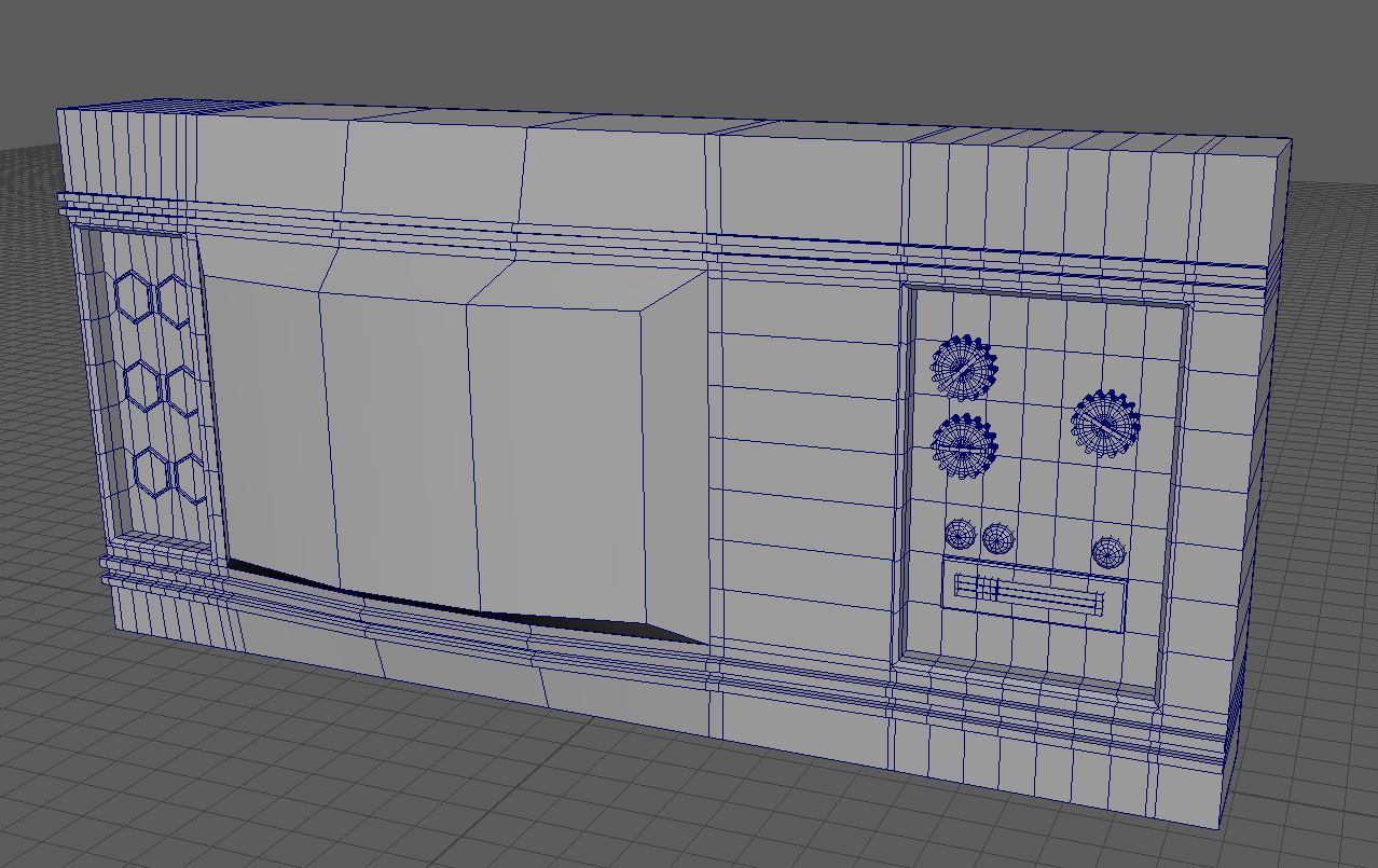
Once I had the body to the correct size I connected the monitor vertex to the vertex of the tv body. Giving me one object with solid topology (Fig.6). Next, I began adding details to the TV front. I began by adding ridges to the face using the multi cut tool, as well as intruding two cuts, which I would use for a speaker and dials respectively (Fig.7).
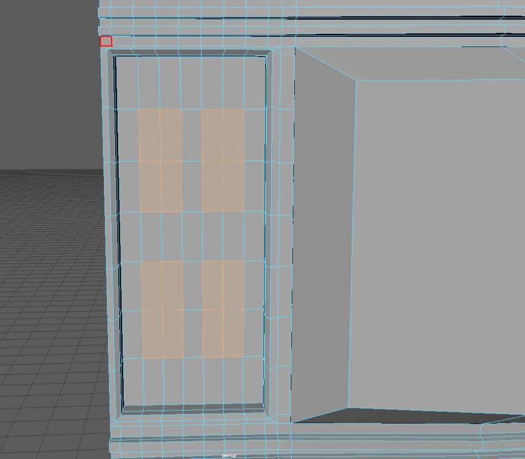
Fig.8 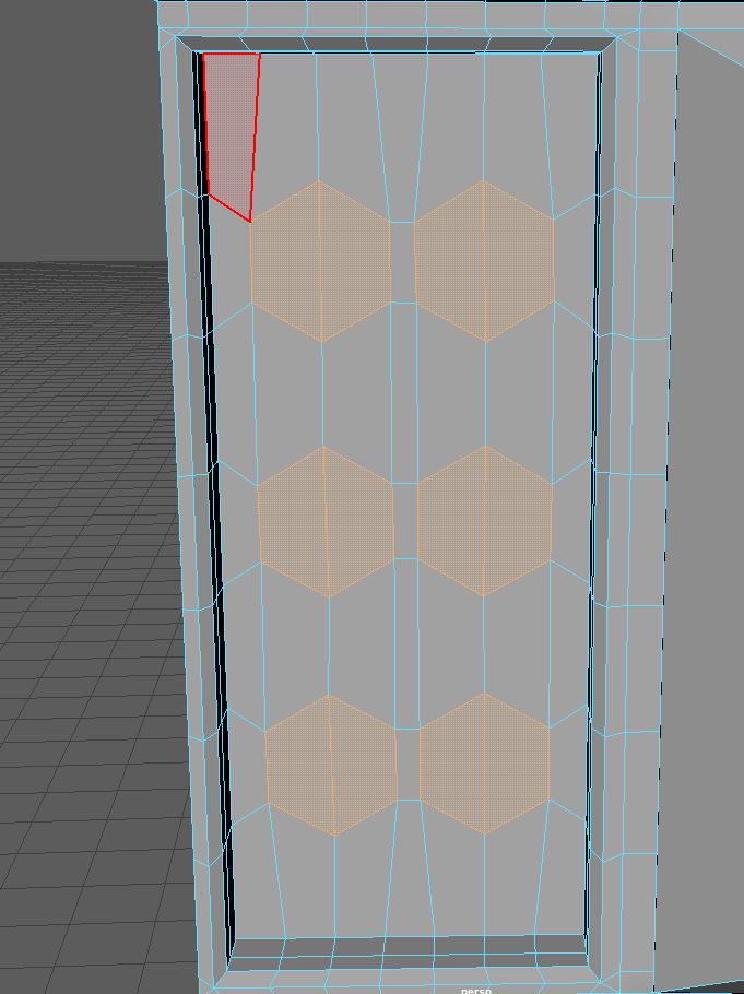
Fig.9 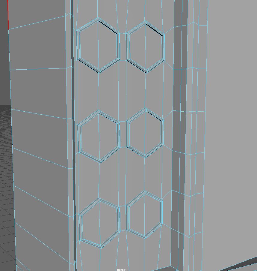
Fig.10
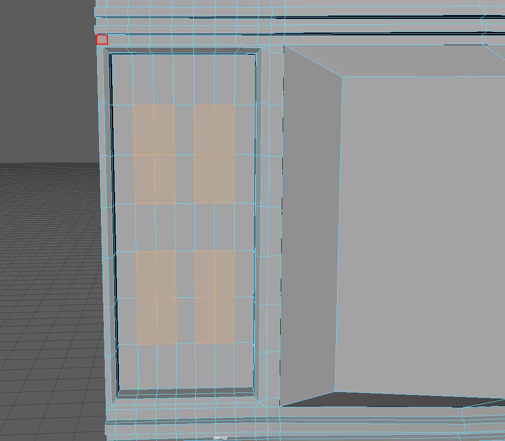
To make the speaker I went for a honeycomb style as I felt that added interest, while still looking simplistic enough to not take away the retro styling of the object. I used the edge loop tool to add many edges into the shape, to which I then chose the faces I would circularise (Fig.8). The results of the circularise tool were quite good, though I did need to rotate these faces to keep my topology as organised as possible (Fig.9). I then extruded these circularised faces and then bevelled the edges, I then intruded the newly created smaller face to give me the honeycomb looking speaker bumps (Fig.10). when I go to texturing, I plan to give this panel a light grey felt look, to make it look more like a speaker grill.
I wanted to add small details to the face of the TV. To this end I created a horizontal slider which I would texture to look like a volume control. I began with a square, to which I used the edge loop tool to give me two edges down the centre of the shape, and used the multi cut tool to give me two edges along the shape in the other direction. After this I intruded the faces either side of the switch to make it look like a slider without the handle (Fig.11).

Fig.11 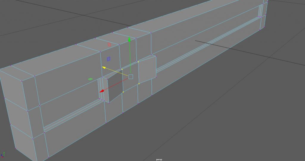
Fig.12 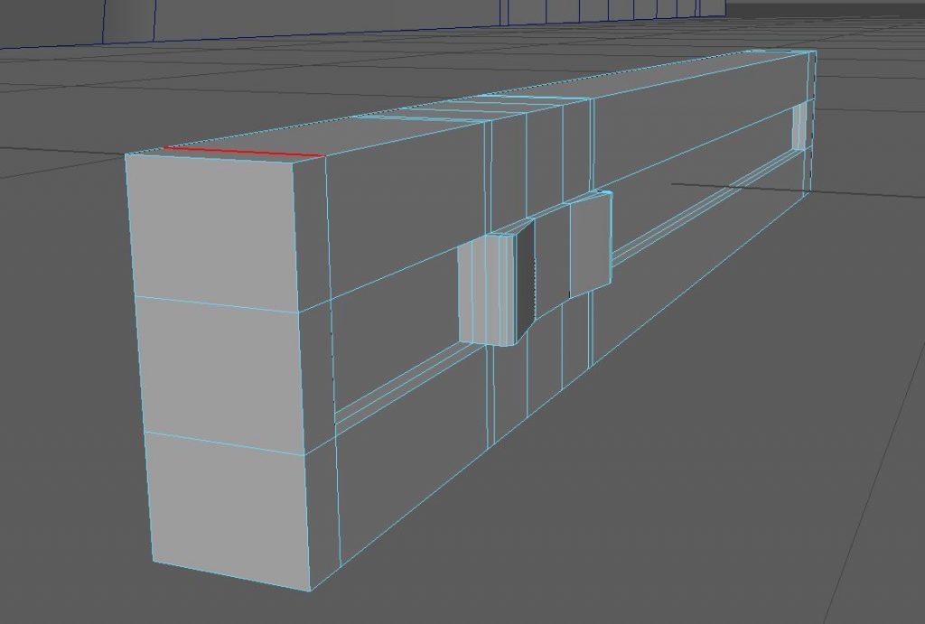
Fig.13
To make the handle I extruded the faces which I hadn’t introverted and added two edge loops in the centre, this gave me two edges which when I selected the vertex I could move inward to give me a nice curved shape (Fig.12). The final touch to make this shape look nice was to bevel the edges, which after having fixed the topology caused by this bevel gave me a finished slider asset (Fig.13).
Next, I added three buttons to the object face, just above where I place the slider (Fig.14). I made these by creating poly cylinders and bevelling the outer edge to a value of one, after this I selected the centre vertex of the outer face and intruded to give a concave effect (Fig.17, background).
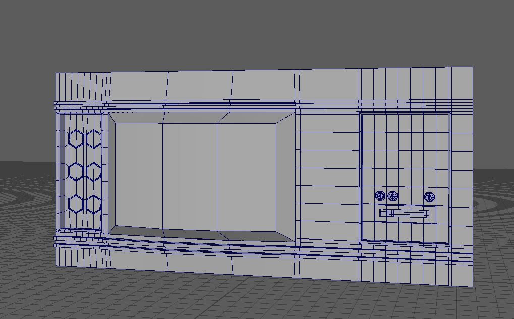
Fig.14 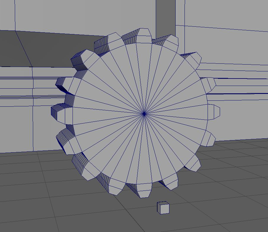
Fig.15 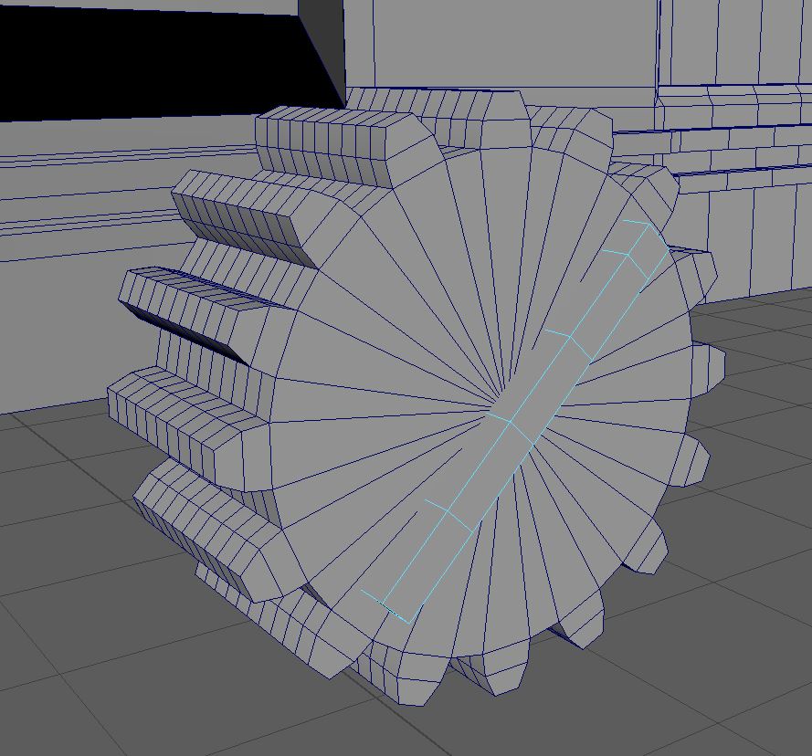
Fig.16 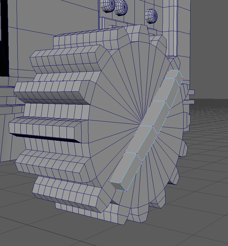
Fig.17
With these buttons made I wanted to make dials to partner them, this would give a more complex design which I felt would look nice. I started with a polygon cog object, which I then connected the faces together (Fig.15). I also created a poly sphere which I extended outward to give a rectangle, also I added two edge loops using the insert edge loop tool to make sure they were evenly spaces and then moved the newly created vertex outward to give a more detailed dial handle. (Fig.16).
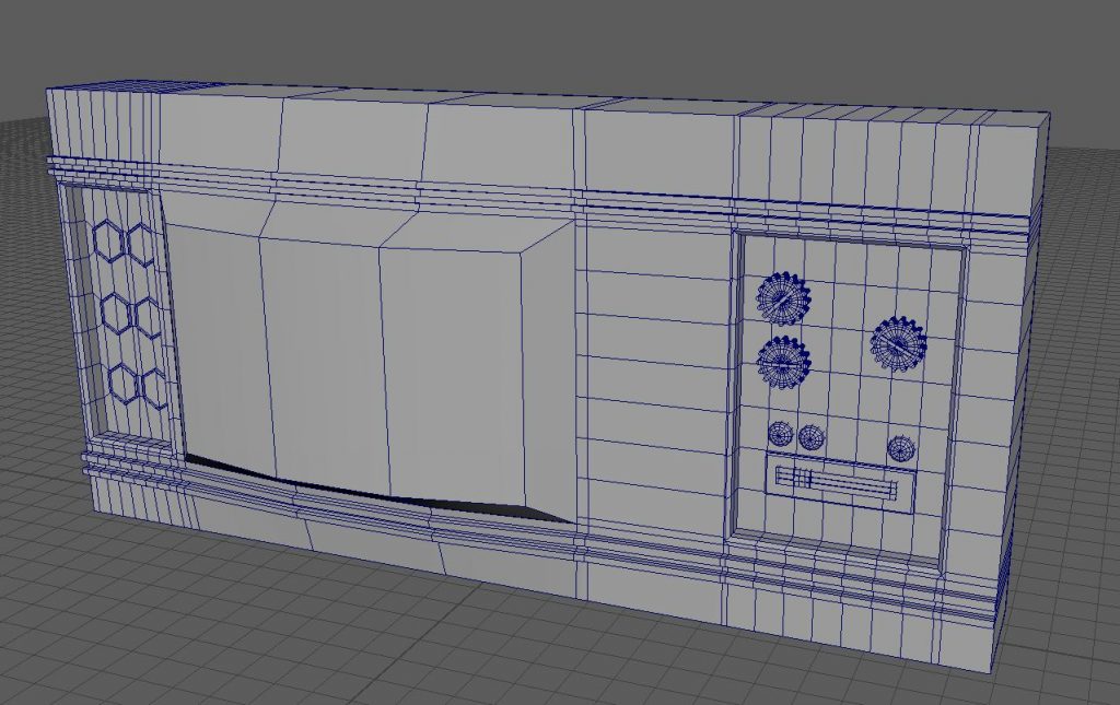
Fig.18 
Fig.19 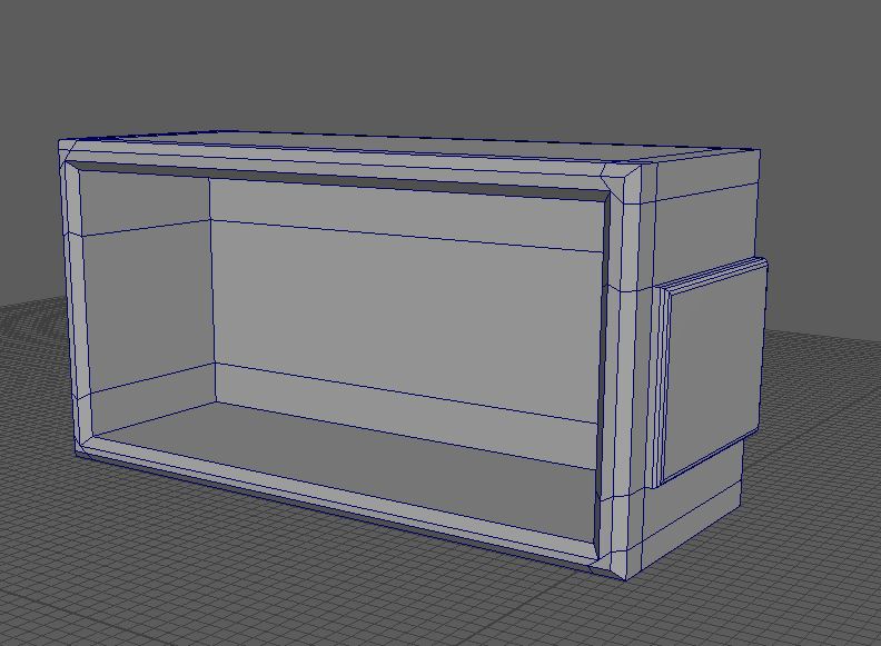
Fig.20
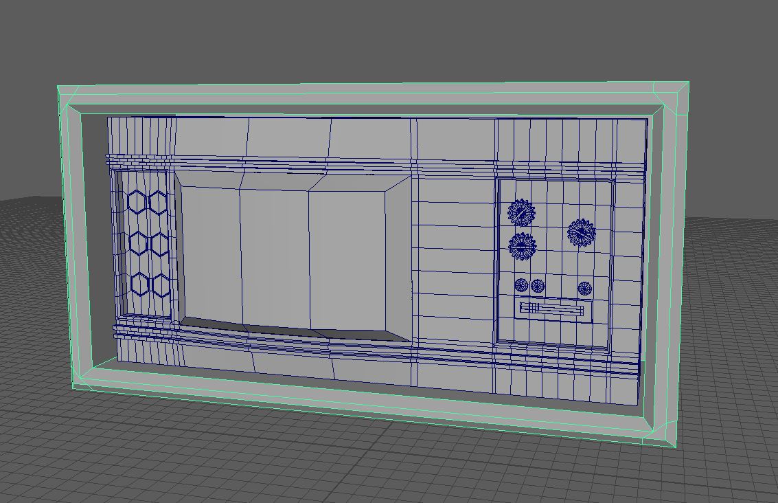
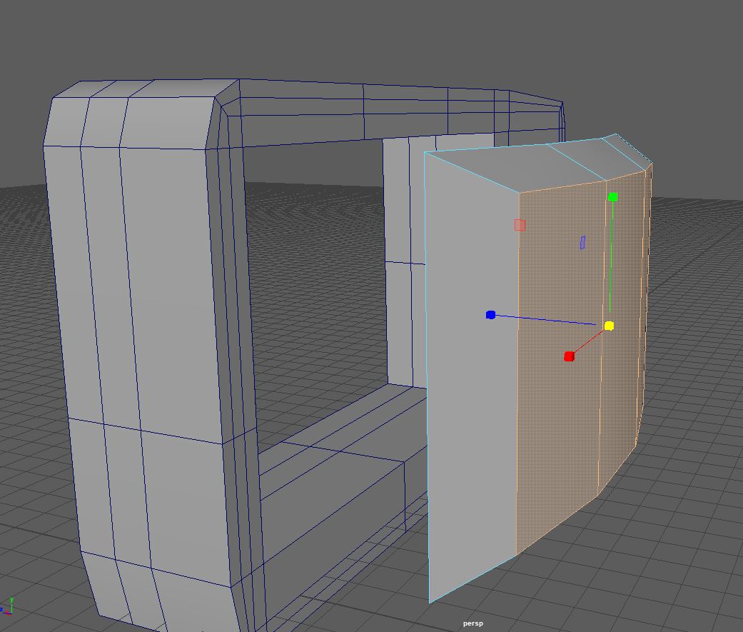
With the details of the TV object put into place, (Fig.18). I turned my attention to the box I wanted to surround it. I created a cylinder, which I then scaled to the size I wanted and deleted the front face. Then I added a thickness of 3 to the object to give me a surrounding box (Fig.19). I also created two side panels which would go on the outside of the box, again this was done simply with a cube which I then sized and bevelled where I wanted (Fig.20). I made these using separate pieces, I know they could have been made with an extrude however I didn’t want to make the UV process complicated and so made them both separate objects. I also bevelled the outside two edges to give a smoothed object. This asset will be baked and as I found with the ceiling light having sharp ends where they are smoothed on the high poly results in black dead space on the final asset. I wanted to avoid this with this model.

Fig.21 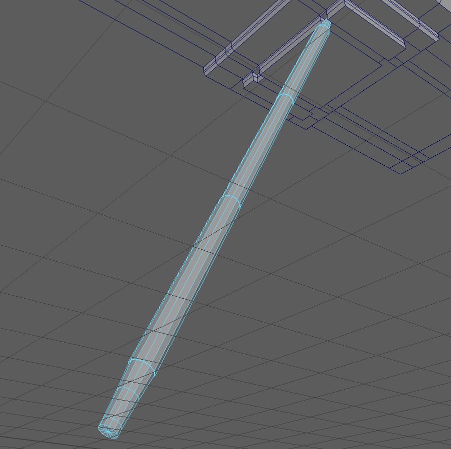
Fig.22 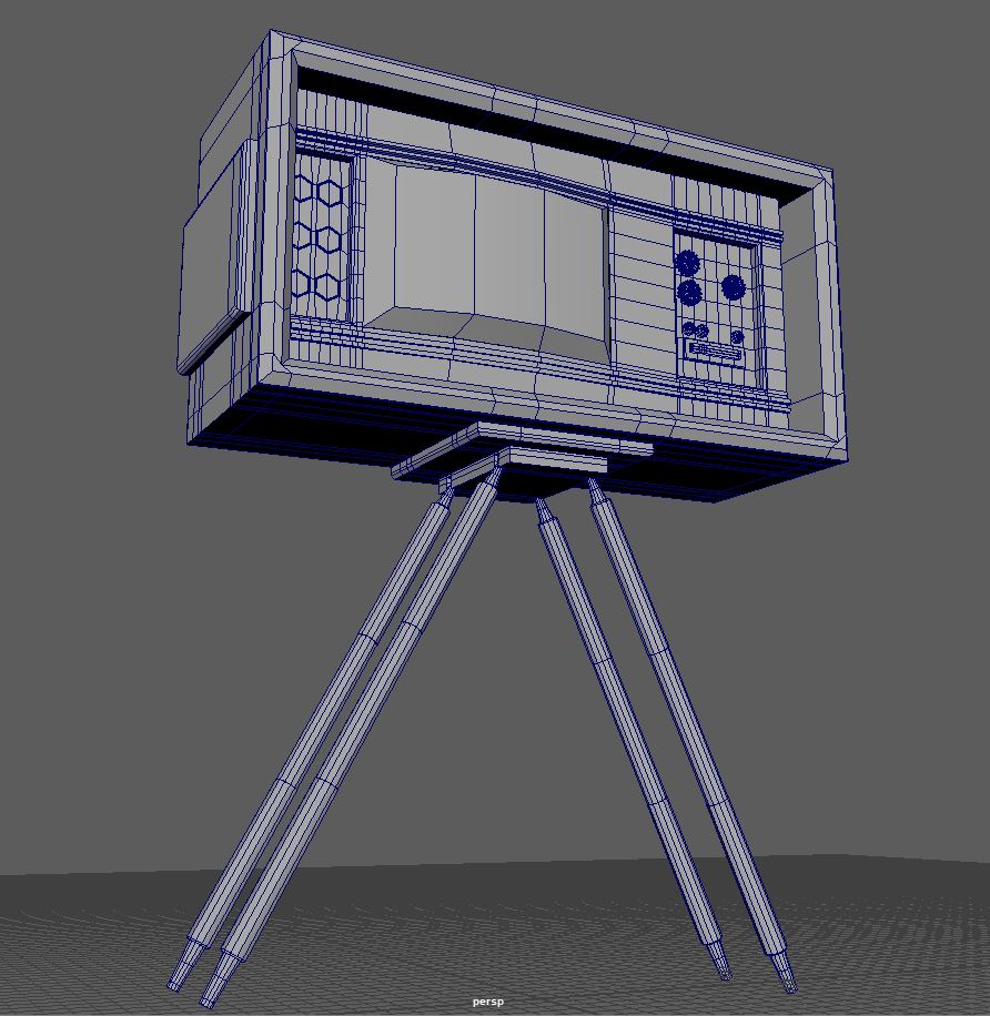
Fig.23
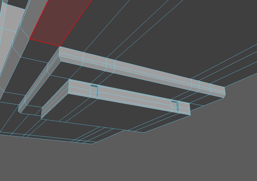
Then I began work on the legs for the object. I made the connecting piece first, as this would give me a guide for how wide I needed the ends of my legs to be. This piece again started with a poly cube which I then scaled to the large size. After this I bevelled the edges and extruded the new face to give the staggered look (Fig.21). With the legs I used a cylinder object and scaled to make long, to which I then added four evenly spaced edge loops, splitting the object into five sections. I then extruded two of these sections by .5, to give the impression of metal being placed over wood (Fig.22). I then simply had to duplicate and place my one leg where I needed it (Fig.23)
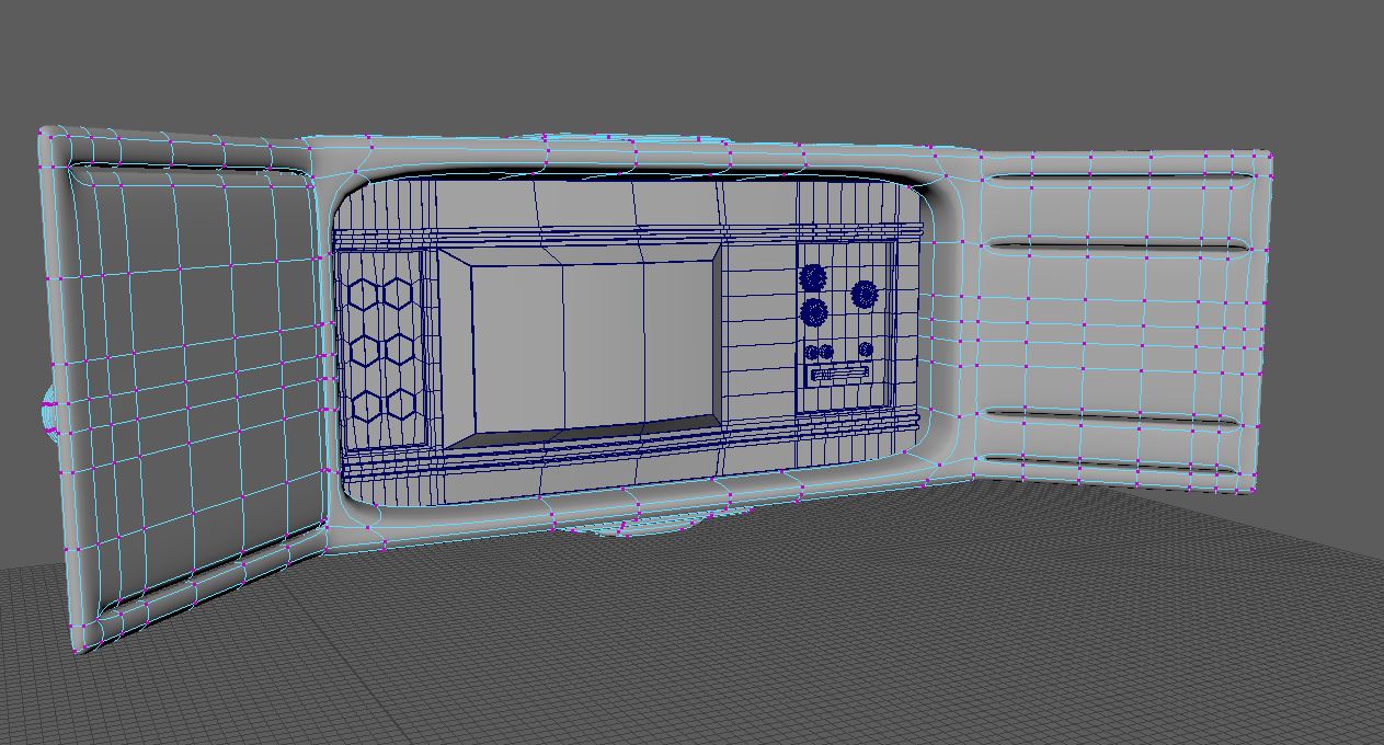
I selected the faces created by the bevelled edges and extruded outward, this gave me two doors which looked like they would sit flush when closed (Fig.25). Then I added edge loops near the ends of these doors and used the circularise tool to make outlines for handles (Fig.26).
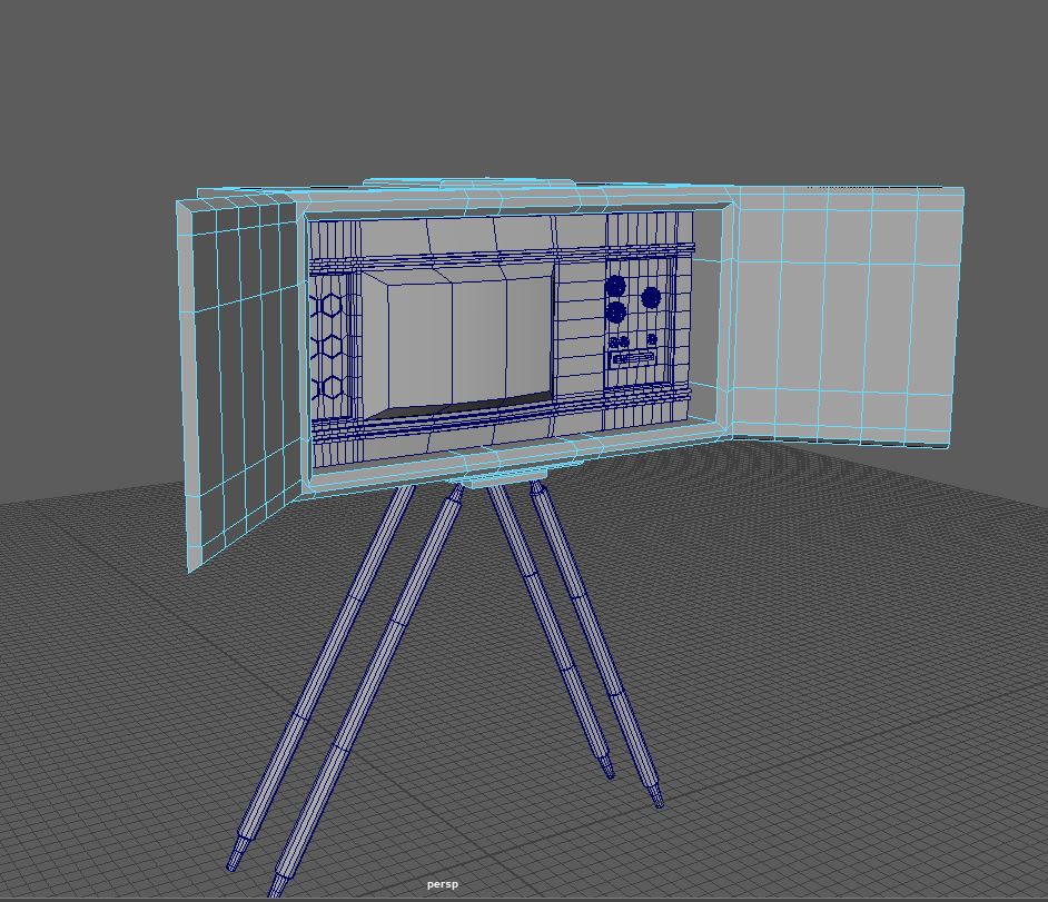
Fig.24 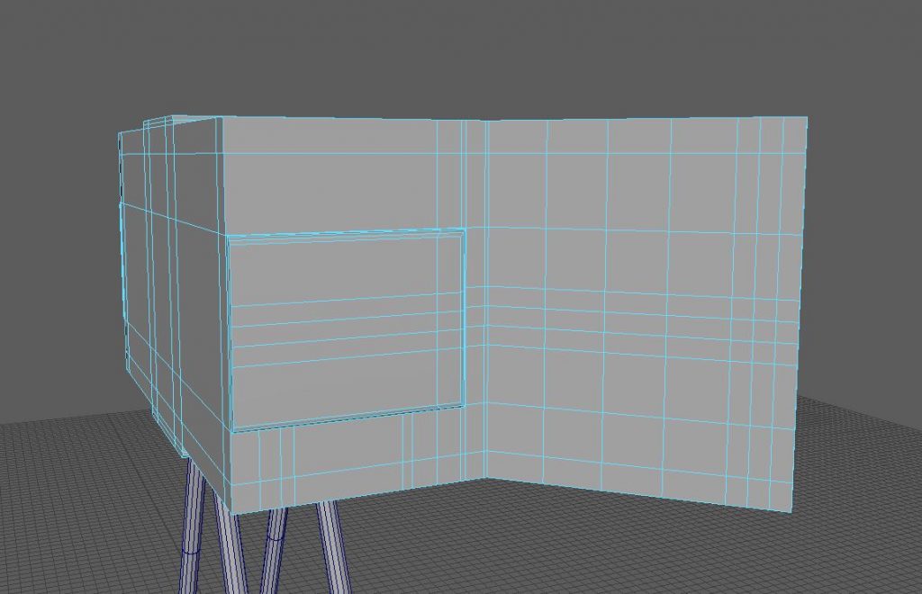
Fig.25 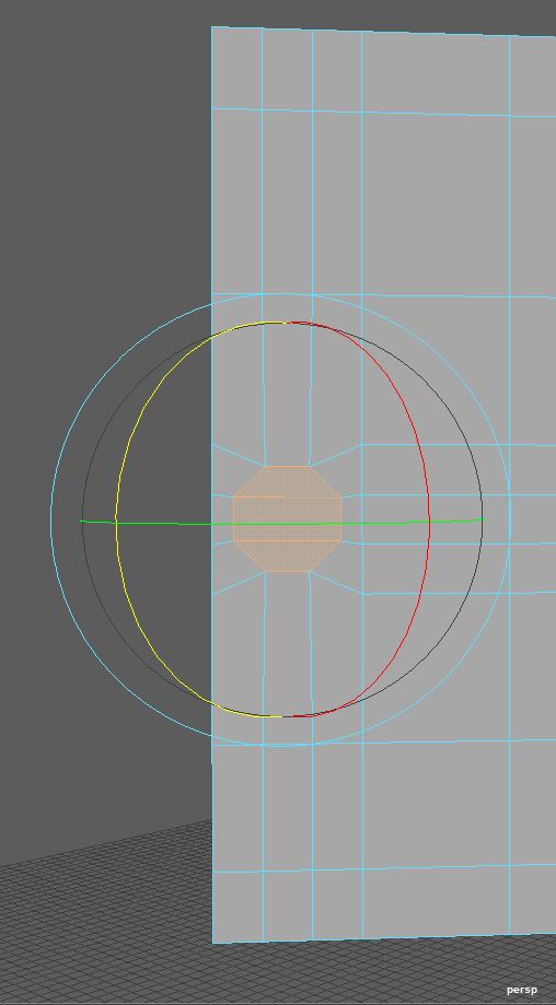
Fig.26 
Fig.27 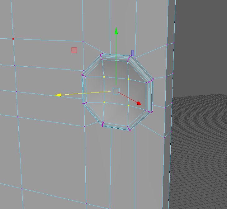
Fig.28
To make the handles for the doors I extruded the newly made circular faces outward and added a edge loop near the end of the created cylinder. This new division I then extended outward to give me a circularized handle (Fig.27). I then selected the four vertex that made up the outward face of these handles and intruded them inward to create a concave shape which I thought looked nice

Fig.29 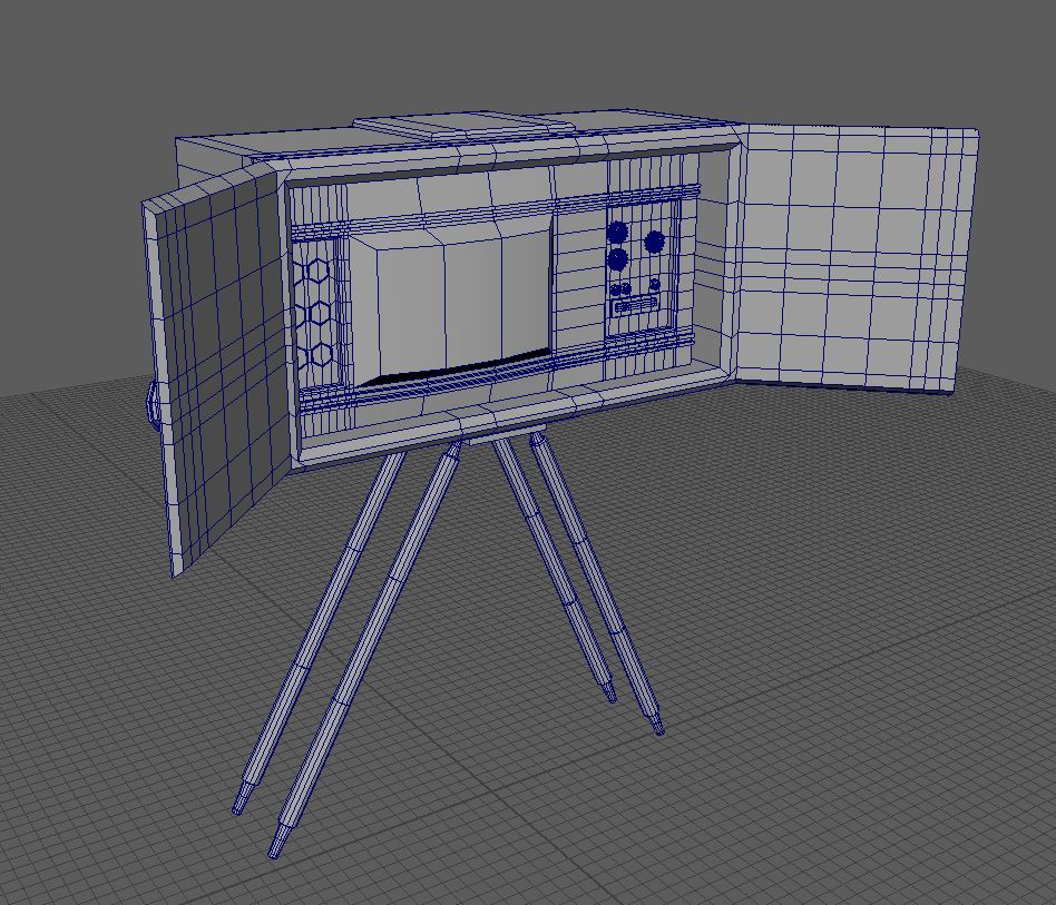
Fig.30
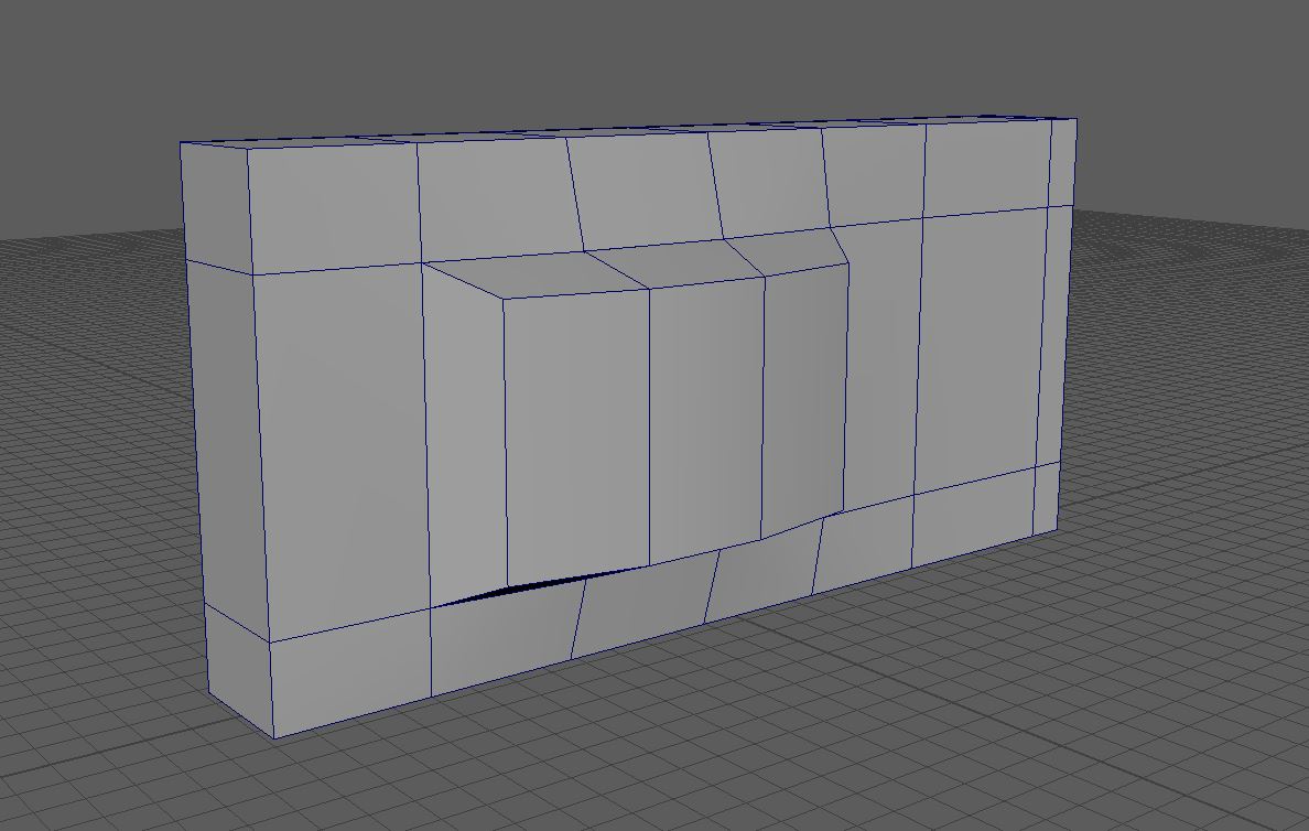
Up until this point I thought the design of this asset was progressing well. However, I soon found out that my original plan wouldn’t be doable as it resulted in issues with my topology I couldn’t fix. Sadly this meant I had to later redesign the outer shell for something I honestly don’t think is as nice as my first design.
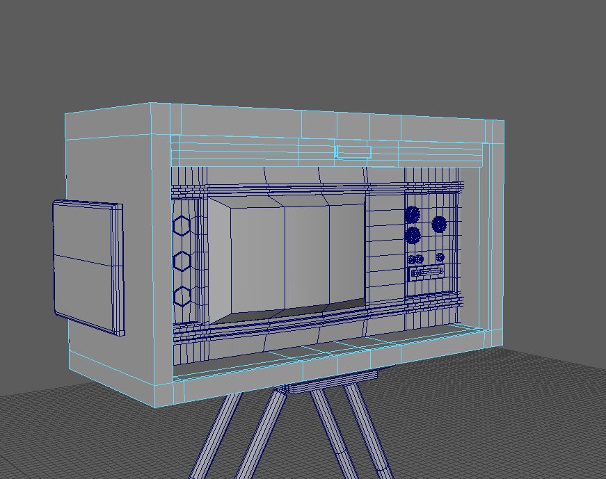
Fig.32 
Fig.33
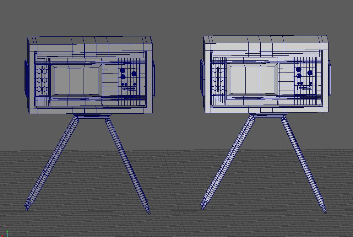
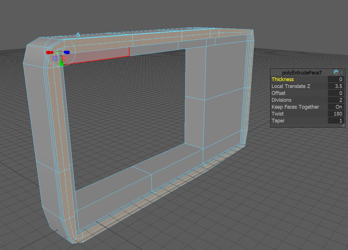
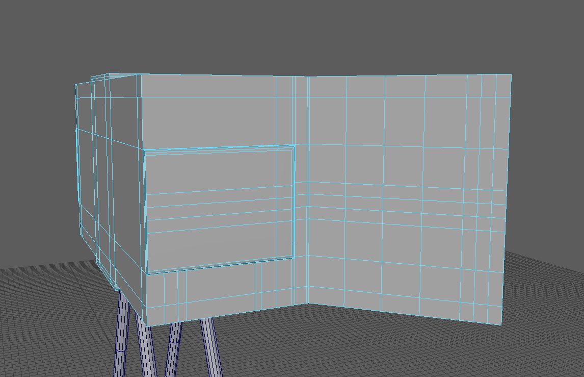
For my redesign I decided that instead of having two doors that sat open either side of the TV I would make a shutter style door. This method didn’t result in strange topology and meant that I would run into problems when smoothing the object, however I do not like it nearly as much as my original design. To make this shutter door I simply added two edge loops near the edge of the case surround and extruded the newly made faces downward to give me the final piece.
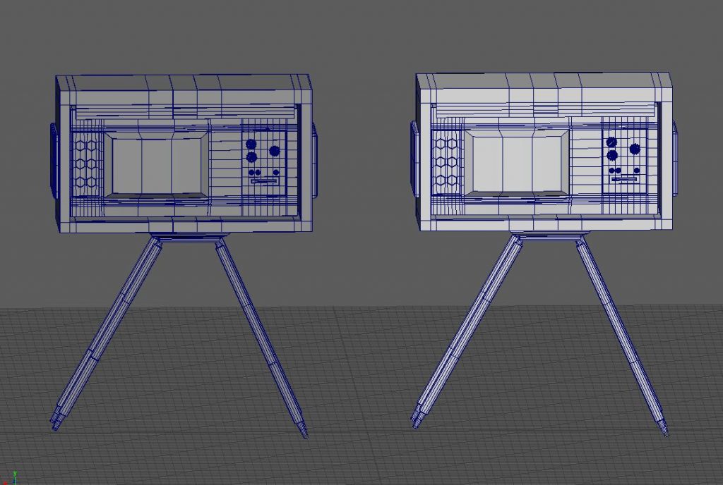
I think overall the design looks okay, but I am annoyed that I couldn’t make the original design work. I will try experimenting with how to make the door design work when I don’t have other assets to do. It was fun experimenting with the circularise tool though, and the method I used to make the door handles I would go on to use in my coffee machine asset. Hopefully in texturing the model will be seen more clearly and be instantly recognisable as an old fashioned TV.
UV
This is the UV I ended with, I did have to do a lot of cutting with this model as many of the bevelled edges and cylinders didn’t work well with the automatic tool.

Texturing
I knew I wanted to use a nice dark wood for the TV surround (Fig.1), and I thought it would be nice to use a lighter shade of wood for the extra pieces dotted around the TV. However with the knowledge that the lighter shade of would didn’t render nicely, I think I would have been better off just using a black plastic for the body of the TV, to help differentiate it from the rest of the wood. As it stands I feel like the TV itself gets somewhat lost amongst the wood of the box.
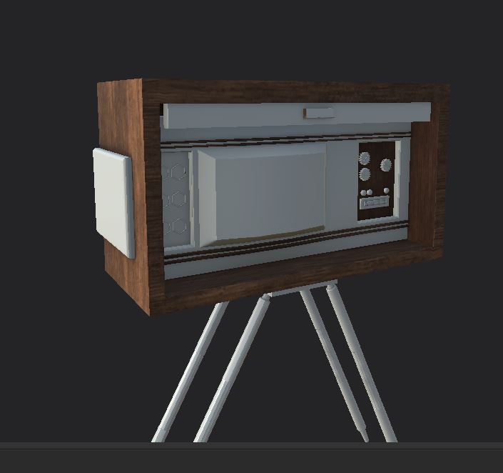
Fig.1 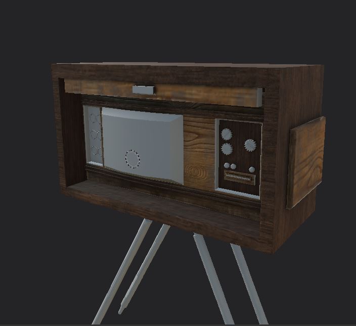
Fig.2 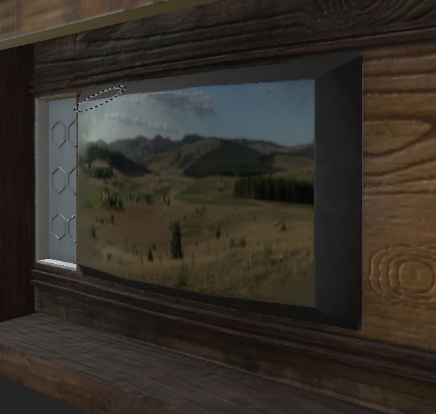
Fig.3 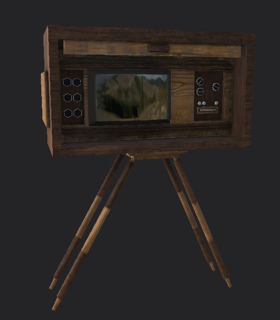
Fig.4 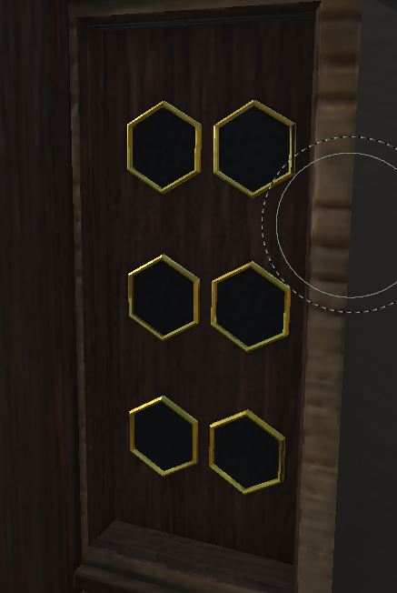
Fig.5 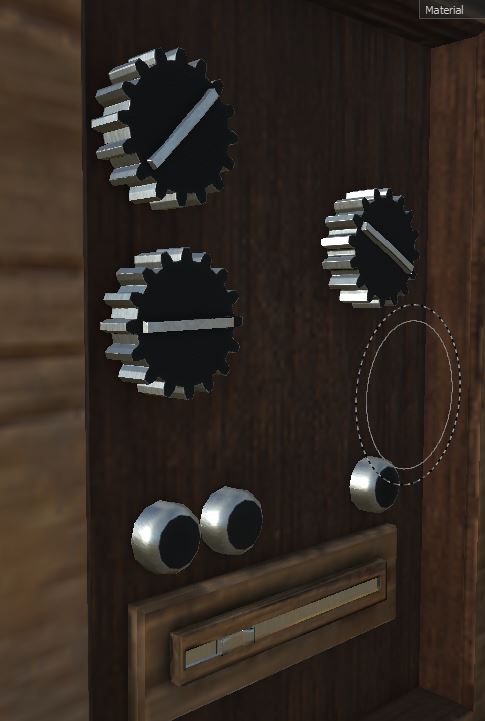
Fig.6 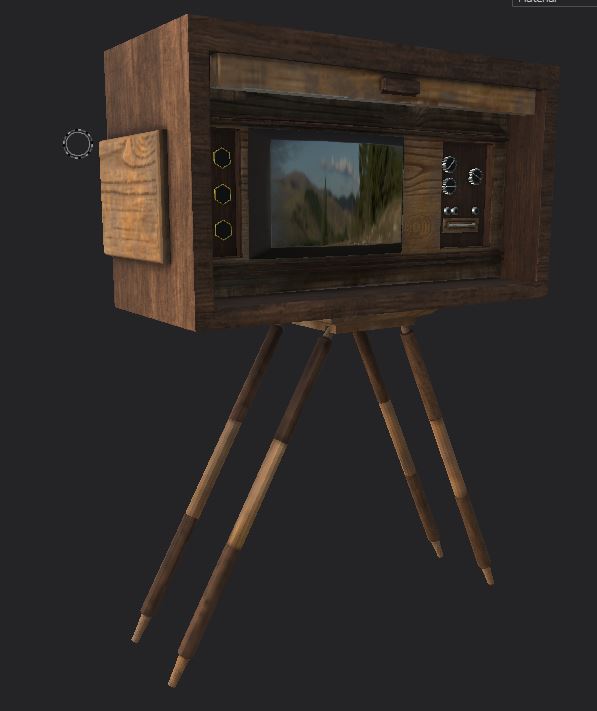
Fig.7
I do think the dials worked nicely and the honeycomb looks nice, however I still don’t think the speaker is as clearly a speaker as it could have been.
Final renders can be found here
References
Brueton,c (2011). Our View Event – Media Focus. Accentuate [Online Article]. Available online: http://www.accentuateuk.org/ideashubblog?offset=12&item=89 [Accessed 24/11/2020]
USHistory.org. (2020). Land of Television. [Online Resource]. Available at: https://www.ushistory.org/us/53c.asp [Accessed 24/11/2020]
Pingback: 3D Art for Games – Wireframes – Post 3 – Booth Seat & 1950’s TV – Fraser Ibbotson – 647603