


This is the reference I used to make my original design. I love the different black end pieces on the body and the clock style face for the gallons used. I also like the light shown above the clock face as I plan to have every asset which would have a light source use one in my assignment 2 video.
Attempt 1
I did have to redo this design like I did the bar stool. Not as much went wrong with this design as did with that model however what did go wrong, I believe is terminal and by the point I had realised my mistakes it was too late to fix them. I also much prefer my second design to my first and am happy overall. My two big mistakes were using a boolean where I shouldn’t have and making a design that was full of ngons.

Fig.1a 
Fig.2a
I began with a basic poly cube which I stretched to make a rectangle (Fig.1a). While the reference is much more of a squared bench, I thought it would look more interesting if I made it a little wider. After I had this shape, I bevelled the edge and extended the new, smaller face outward to give a two tiered look (Fig.2a)

Fig.3a 
Fig.4a
After this I made another poly sphere and manipulated it to give me the tall body of the pump. To this I added a ring for my clock face, extruded the vertex to give a kick plate to the design and fashioned a hook and hole area for where the nozzle will go, (Fig.3a). Here I made my first big mistake. When adding in the edges needed to extrude and intrude, I made ngon shapes which when I later smoothed the mesh gave me a poor result. To add to this I later Boolean along this face which resulted in me not being able to add supporting edges with the multi cut tool.
Here I also duplicated the design and forged a shoulder piece in the same way I did with the foot piece, (Fig.4a). At this point I still was not fully sure how I was meant to make a low poly of the high poly design and so believed the best way to do this was by making both as I went along. I know believe the best way of doing this is to make the low poly, then duplicate the finished low poly and add the smoothing support edges to form a high poly.

Fig.5a 
Fig.6a
Next, I formed the connecting piece between the shoulder shape and where I would design the sign. I used a basic poly cylinder and added a multi cut ring near the top which I then extruded around to give more interest. (Fig.5a)

Fig.7a 
Fig.8a 
Fig.9a
With this finished I turned my attention to the sign. I didn’t want to use the same sign as is in the reference, but I wanted something that incorporated light for when I place all my assets in one scene. I began with a basic poly sphere which I extruded outward (Fig.7a), after this I used a multi cut and extruded upward (Fig.8a), pausing and rotating the face I was working on occasionally to give a nice completed horse shoe look, (Fig.9a). Another mistake I made here was where the faces join I extruded the object into itself. I had thought that the Boolean tool would fix this however learnt that I should have stopped extruding with the faces near each other and then merged vertex points to form one shape.

Fig.10a 
Fig.11a
I then formed the light shown in the reference images. I cut a small face in the body of the design, which again resulted in ngons, extruded this face and rotated it to make a shape resembling that of the reference image, (Fig.10a). After this I cut another, smaller face into the now extruded surface and intruded (Fig.11a), this would have been the place I placed the light source once I had textured the model.
Then I made the sign and the lighting part of the object. For the sign I used two cylinders and a cube which I arranged as shown above, (Fig.12a). I also used the same extruding and rotating method as I used when making the sign to add two mirroring mounts on which I wouldn’t have added additional light sources (Fig.13)

Fig.12a 
Fig.13

With the sign finished I added the hook to the nozzle stand (Fig.14). This then gave me the shape seen in (Fig.15). In this image you can see a diagonal line in the base shape. This I because I had booleaned the base shape to the body shape. This as I later found out was a mistake as I couldn’t add any multi cut lines to that face so when I smoothed the design my geometry was damaged.

Fig.14 
Fig.15


Next I turned my attention to the nozzle. I found a lovely reference which showed me how the trigger mechanism of a fuel nozzle works. This was a very complicated shape and so I decided to simplify it a little in my design.

Fig.16 
Fig.17 
Fig.18 
Fig.19 
Fig.20 
Fig.21


I then intersected the previously made shape with this new object, (Fig.18) and then extended the two faces at the centre of the sphere (Fig.19). This gave me a nice shape which I could use to connect to the trigger once I had placed it. When making the trigger I again used the extrude and rotate method to give me a unique shape which fit my design (Fig.20). With this I moved the vertex left of the far face of the sphere object until it intersected with the trigger and booleaned these together (Fig.21).

Fig.22 
Fig.23 
Fig.24
After this I placed the nozzle where it would sit on the final model, (Fig.22). Here I didn’t mind that the hook I made intersected with the hand guard as that is how they are secured on the reference I used (Fig.23). I also added a little detail to the top of the sphere, just to give the nozzle more interest. I then fashioned the end into a more ornate piece where I would attach the hose. (Fig.24) I also made a hose attachment which I added to the body of the asset. You can see in the picture (Fig.24) that I booleaned this piece to the body, this was another mistake as it meant I couldn’t add smoothing lines to the design after I had finished it.

Fig.25 
Fig.26 
Fig.27
For the hose I began with a pencil drawn curve (Fig.25), to which I then manipulated the vertex points to give me a nice natural curve (Fig.29). Once I had this, I created a cylinder and deleted all but one of the flat faces. This I then lined up centrally with he curve line and extruded along the path. This gave me a very nice hose which I would texture with a cloth covering as that is what old fuel hoses used as their sleeves (Fig.27).

Fig.28 
Fig.29
At this point the building of the model was completed and I turned my attention to crafting a high and low poly version. I deleted many of the edges present in the hose and the nozzle for the low poly, (Fig.28). Then tried to add supporting edges to the high poly. It was here I realised my big mistake with the Booleans and as you can see in (Fig.29). I ended with one edge of my body damaged and unable to correct it.
I liked my design however knew that I could do better and that I would have to redo it so as to correct my mistakes.
Attempt 2
I didn’t want to just remake the same design I had previously made, so I had a look at different references and found different elements I used in my second model.


I really liked the extra supports of the side of this design, and I brought them into my design, just with smoother edges.


I loved the way the hose was connected to the pump in this reference. I like using the strut between the body and the sign for something more than decoration and thought it really interesting having the hose curl around the design.

Fig.1b 
Fig.2b
I used the same file to recreate my pump, hiding and deleting the parts of the old design as I remade them. I started with the hook, which I remade as its own piece (Fig.1b). There was little benefit to having this piece be conjoined to the body and so I decided to leave it separate. I kept the fuel nozzle, as I felt like it would work with my new design just as well as it did the original (Fig.2b).

Fig.3b 
Fig.4b 
Fig.5b

Next, I recreated the shoulder piece. I remade this piece as I had booleaned the other which meant I couldn’t add multi cuts. I made it look the same however, I didn’t see a problem with the design just how I had achieved it. The extruded cut I lowered and made larger (Fig.3b), to which I added a horizontal cylinder (Fig.4b) and added a cylinder the hose could connect to, (Fig.5b). I made this connecting cylinder more interesting with two extruded and bevelling the edge. I also intruded the edge so that where the hose connects to the body will be obscured from the viewers eye.

Fig.6b 
Fig.7b
With the sign I wanted a more simplified design, which would help make the final piece look like something which would have actually have been used in the 50’s. I used a basic square, to which I extruded both sides in the same technique to the same levels. Thus, giving me a symmetrical design that lines up well (Fig.6b). Having learnt from my mistake with the previous sign I stopped the faces, so they were a tiny bit apart from each other and merged the four vertex that made the separate faces (Fig.7b). This gave me one piece that smoothed well and had no faces colliding with each other.

Fig.8b 
Fig.9b 
Fig.10b
Then, I started working on the face of the body. I liked the face design I had in my first model and so used the first reference again. I started with a simple frame, to which I will add the detailing of the clock face in texturing (Fig.9b). Then I implemented the idea I got from the Polly pump I looked at and added a support to either side of the body (Fig.9b), I added a bevel to the top and the sides of these struts as I thought that looked a little more complex than was in the reference. After I had made these, I decided to add a similar support to the front o the shape, which I thought helped add to interest. (Fig.10b)

Fig.11b 
Fig.12b
I finished by making the hose. I used the same method as I did in the first design, a pencil drawn curve which I manipulated into giving a nice organic curve (Fig.11b) and then placed it so it merged with he body and the nozzle (Fig.12b).

Finally, I extruded one of the internal faces of the sign, I extruded to just over halfway of the design ad bevelled the edges. When I texture, I will be placing a fake brand name along this plane and adding lights into the ridge of the gap, which I believe will give a nice effect.
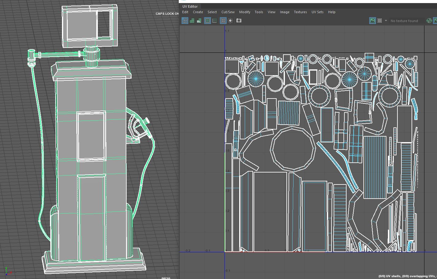
UV
I didn’t make this pack by making one model and following it through to the end, instead I modelled them all, then UV’d them and textured them all before finally rendering them all. Because of this by the time I Uv’d this model I had finally worked out how to cut the model up appropriately.
Texturing
There were a few issues with the baking of this model, mostly around the hose, nozzle and hose connector. I’m not entirely sure why these parts didn’t bake well when the rest of the model worked fine. I cant see anything wrong with my UV, but there must be something. I ended up hiding these elements using dark steels and rubber for these parts.
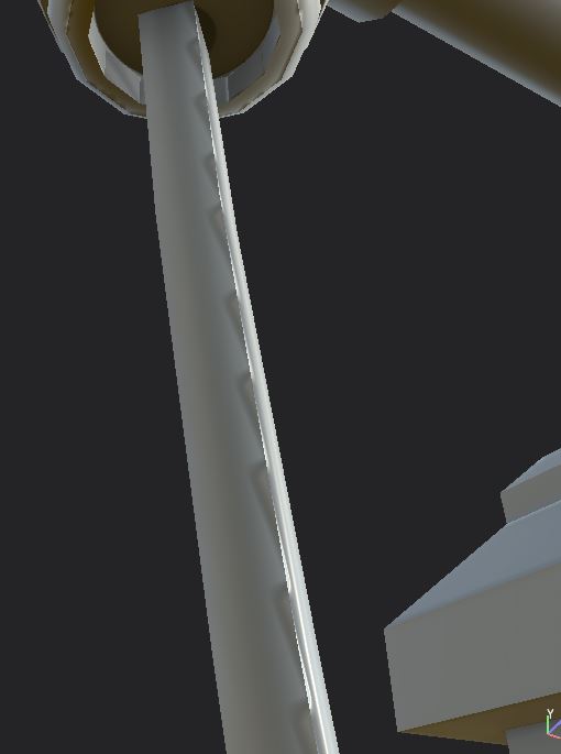
Fig.1 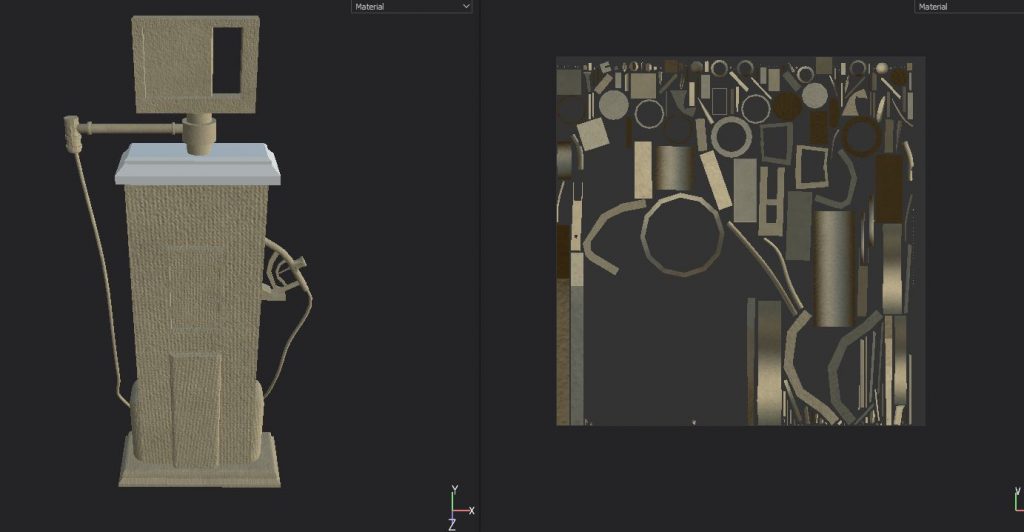
Fig.2 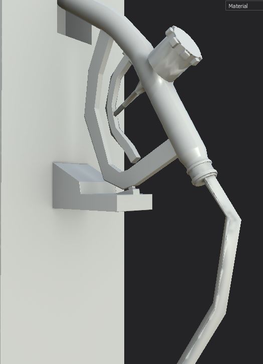
Fig.3 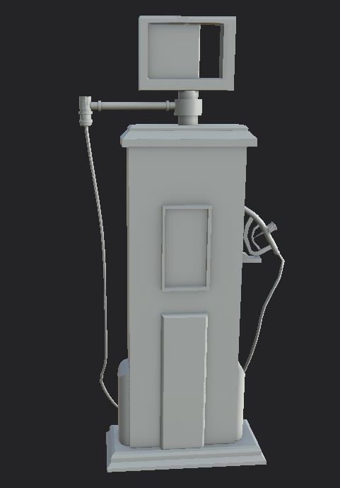
Fig.4
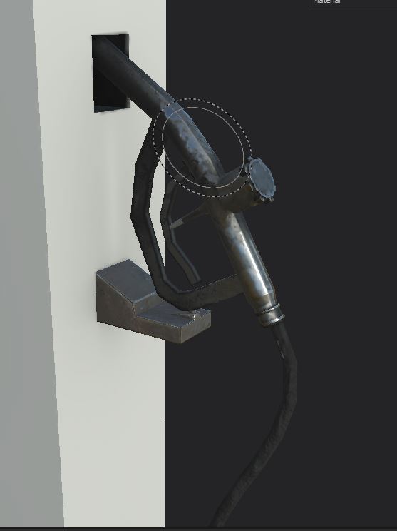
Fig.5 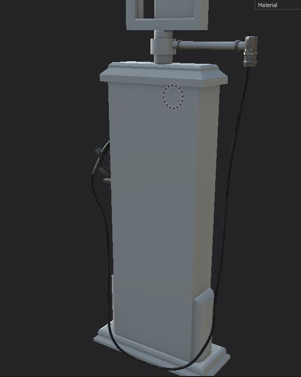
Fig.6 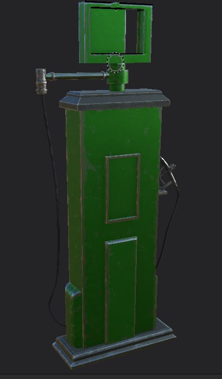
Fig.7 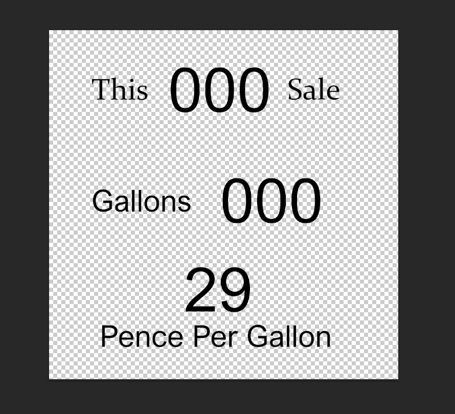
Fig.8 
Fig.9
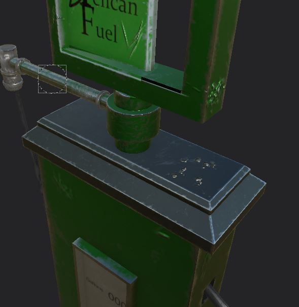
Fig.10 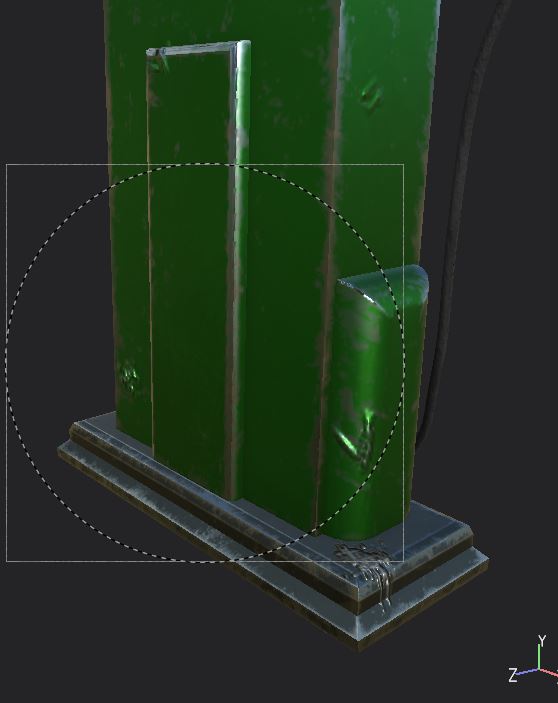
Fig.11 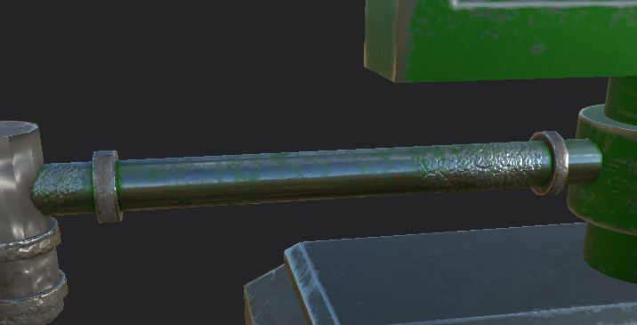
Fig.12 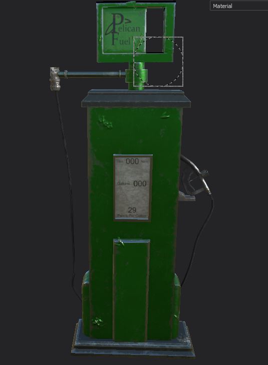
Fig.14
This was the first model that I used stencils on, and I found it to be a very confusing process however I do think they really complete the design. Along with the subtle different tools used to add wear and tear I think really makes the model stand out amongst the others.
The final renders of this asset can be found here
References
Automobilia UK [Sales listing]. Available online: https://www.automobilia-uk.com/products/vintage-pumps-globes/wayne-dial-face-vintage-1930-s-pump- [Accessed 05/11/2020]
Matt’s Automobilia [Product] ‘VINTAGE PETROL PUMP -GILBARCO RESTORED PUMP WITH BP LIVERY ADDED #4207‘. Available at: https://mattsautomobilia.co.uk/product/vintage-petrol-pump-gilbarco-restored-pump-with-bp-livery-added-4207 [Accessed 21/12/2020]
Polly Fuel Pump [Ebay Listing]. mtgames (Seller). ‘VINTAGE PETROL PUMP WAYNE 60 WITH POLLY GAS LIVERY #3437 SN 27‘. Available at: https://www.ebay.co.uk/itm/VINTAGE-PETROL-PUMP-WAYNE-60-WITH-POLLY-GAS-LIVERY-3437-SN-27-/293100366794 [Accessed 21/12/2020]
RiverRat Antiques. [Sales Listing[ Vintage 1940s Morrison Brass Gas Pump Nozzle FIG. 227C. Available Online: https://www.riverratantiques.com/listing/537536216/vintage-1940s-morrison-brass-gas-pump [Accessed 06/11/2020]
Pingback: 3D Art for Games – Wireframes – Post 2 – Fuel Pump & Phone – Fraser Ibbotson – 647603